Is a mine of a rolling developed from small to big, it has 35 years of mining history of deep mining of large gold mines. At present, the new exploration has a resource reserve of (332+333) of 45 million tons and an average gold grade of 3.33g/t. The maximum buried depth of the deposit is more than 1400m, which consists of three relatively independent mining areas, of which the old mining area is planned to expand to 10,000t/d. This paper will study and design the deep well mining related systems such as mining method [1-5], development transportation and lifting system [6-9], ventilation system [10-16], filling system [14-16].
    1 mining method
    1.1 Mining method selection
    The mine is a precious metal deposit with high grade and has villages, highways and diversion channels on the surface. In order to recover mineral resources safely and efficiently, it is necessary to adopt advanced, efficient and safe mining methods to achieve environmental protection, energy saving, high efficiency and low cost. aims. According to the use of mining methods for many years in the mine, the track-free equipment mechanized upward-level layered tailings cement filling and filling mining process is mature and reliable, adaptable, high degree of mechanization of the mine, easy to operate, and can effectively suppress the unfavorable factors threatening mining safety. Improve the utilization rate of ore, reduce the indicators of loss and reduce the cost of land acquisition, etc., which is conducive to environmental protection and save investment.
    Therefore, the research design still recommends mechanized upper-level horizontal tailings cementing filling mining method for trackless equipment (see Figure 1).

    Different arrangements are adopted for different thickness ore bodies: the ore body with thickness greater than 7.5m adopts vertical strike arrangement. The mining plan accounts for 83% of the total ore deposit of the mine; the thickness of the ore body is less than 7.5m. The ore body is arranged along the strike, and the mining plan accounts for about 17% of the mine's total ore. The mining structure and mining engineering of the mining method are introduced below in a vertical orientation.
    1.2 ore structure
    The panel is used as the mining unit and the mining and cutting engineering arrangement is carried out. The length of the panel is 90m and the width is the thickness of the ore body. A number of mine houses and pillars are arranged along the strike. The width of the mine is 8m, the width of the pillar is 7m, the height of the stope is 3.3m, and each of the three layers is a segment with a segment height of 10m. In one step, the mining room is first used, and all the mining houses are harvested after the mining is completed.
    1.3 mining and cutting engineering
    The mining tunnel and the section roadway are excavated in the lower part of the ore body, and the excavation road is accessible from the section roadway. The section of the road is 3.4m×3.3m.
    Through the approach road, the horizontally bottomed roadway is drilled vertically in the ore body. The section of the roadway is 4m×3.3m, and then the width of the mine is enlarged to the width of the mine (column) to form the bottom layer. A manned filling ventilation patio is arranged on the upper side of the stope. The approach road starts from the sectioned contact road and then digs to the ore body with -20% slope. With the layer-by-layer mining, the layer-by-layer approach is formed to form the layer-by-layer stopway approach to meet the requirements of each layer of the mining approach. The final slope of the field approach is +20%. After each 3 layers are collected, the road is re-introduced into the stopway.
    3 develop transportation and upgrading system
    The existing middle section of the mine has a height of 50m, which is basically adapted to the occurrence state of the ore body and the proposed mining method. Therefore, the design of the study still sets the height of the middle section to 50m, and a medium transportation section is set every 100m. After research, the use of ore concentrated lifting, assisted to improve the use of partitioned layout shafts and supplemented by the slope layout of the development of the vertical projection system shown in Figure 2.

    (1) The main well. The wellhead elevation is +33m, the bottom elevation is -1395m, the well depth is 1428m, and the wellbore has a net diameter of 6.8m.
    The wellbore is equipped with a 21m3 double bucket lifting system and a double-layer cage with a counterweight lifting system. Responsible for the upgrading of 10,000t/d ore in the whole mine and part of the waste rock and the decentralization and upgrading of some personnel materials.
    (2) Auxiliary well 1. The auxiliary well 1 is a cage shaft, the elevation of the wellhead is +15m, the bottom of the well is -1260m, the depth of the well is 1275m, and the net diameter of the wellbore is 7.5m. The wellbore is equipped with a double-layer cage with a counterweight lifting system and a glass-steel ladder and cable room. It is mainly responsible for the lifting tasks of waste rock, personnel and materials in the 1 pit of the new mining area; it also serves as the main channel for laying down the wind, electricity and fresh air.
    (3) Auxiliary well 2. The auxiliary well 2 is a cage shaft with a height of +13m at the wellhead, -1255m at the bottom of the well, 1268m at the depth of the well, and a net diameter of 7m at the wellbore. The wellbore is equipped with a set of double-layer cages with a counterweight lifting system and a glass-steel ladder and cable room. It is mainly responsible for the lifting tasks of waste rock, personnel and materials in the pits of the new mining area 2 and the old mining area; it also serves as the main channel for laying down the wind, electricity and fresh air.
    (4) New return to the wind well. The elevation of the wellhead of the Xinfengjing is about +13m, the elevation of the well bottom is -1230m, the depth of the well is 1243m, and the net diameter of the wellbore is 7.5m. There is a FRP ladder in the well as a return air well in the pit of the Tengjia mining area and also serves as the second safe exit.
    (5) The main chute and the broken inside the pit. Two main ore wells are arranged near the main well, and one main waste slip is used. The dumping chamber is set up at -1230m, and the bottom of the chute is equipped with a crushing system inside the pit.
    (6) The main slippery shaft of the mining area. In the base period of the new mining area, there are 2 main chutes in the mining area, which serve as the ore concentration transfer chute of the new mining area 1.
    In the base period of the new mining area 2, there are 2 main chutes in the mining area, which serve as a centralized transfer and transfer of ore in the new mining area 2 and the old mining area.
    2 ventilation system
    The new mining area 1, the new mining area 2 and the old mining area jointly mining, forming an organic combined large production system. In order to ensure ventilation quality and save ventilation costs, the design uses a district ventilation system, and the three mine areas form their own independent ventilation systems. At present, the old mining area has formed a complete ventilation system. Considering that the production capacity of the mining area is gradually reduced, its ventilation system can meet the production requirements. Therefore, this paper focuses on the systematic research and design of the ventilation system in the new mining area and the new mining area.
    According to the conditions of the deposit and the selected development system, mining sequence and mining method, the auxiliary well 1 and the auxiliary well 2 are respectively arranged at the two ends of the new mining area 1 and the new mining area 2, and the new return air well is arranged in the two mining areas. intermediate. Both mines are mined in the middle and middle sections, both of which are the first two sections -730m and -930m. Based on the principle of safety, reliability, energy saving and high efficiency, the two-wing diagonal extraction ventilation system is adopted. The multi-stage station plan is adopted for the setting of the fan, and the class I station is set in the return zone of the new mine area 1 and the new mine area, and the class II machine station is set in the wellhead of the return air well.
    The air volume in the middle section of each mining area is regulated by the fan boosting and drag reducing.
    According to the mine production schedule and the required wind point layout, the new mine area 1 requires a wind volume of 306 m3/s, which is basically entered by the auxiliary shaft 1, and the slope is slightly entered. The new mining area 2 requires a wind volume of 154 m3/s, which is basically entered by the auxiliary well 2, and the slope is slightly entered. The fresh air passes through the middle section of the transportation lane, the middle section of the pipeline into the wind shaft, the section roadway, and then to the stope. After the fresh air enters the stope to clean the working face, the dirty wind is filled into the wind well, and is discharged into the return air shaft through the upper return airway and concentrated into the return air well to discharge the surface.
    In addition, the air volume of the crushing loading system and the old mining area is temporarily estimated at 90m3/s, and is shared by the auxiliary well 2 and the old mining area air intake system, wherein the auxiliary well 2 is estimated to be 50m3/s.
    The main technical indicators of the ventilation system are shown in Table 1.

    4 filling system
    A filling station is built on the surface of the old mining area, and a vertical sand silo self-flow pipeline conveying and filling system is adopted. It is estimated that the system can meet the filling needs of production in old mining areas. Therefore, there is no need to rebuild the filling station in the old mining area.
    The new mining area filling station is located near the auxiliary shaft 2, and the filling capacity is designed according to the filling requirements of 6000t/d production capacity. There are 4 sets of 90m3/h filling preparation system in the station. Two systems work simultaneously during normal filling.
    After beneficiation plant tailings hierarchical classification station, the underflow is pumped to a filling station now. Filling pipeline process: filling slurry filling port → filling drilling (new construction) → filling contact lane → slope road (new construction) → Tengjia → 630m horizontal slope crossing → return wind lane → filling pedestrian ventilation patio → mining yard.
    5 Conclusion
Taking a large-scale deep mine as an example, this paper systematically introduces the research and design of its deep mining system such as mining method, development transportation and lifting system, ventilation system and filling system, which can be used as reference for deep mine mining research and design.
    references:
    [1] Xu Zhenhua, Qiao Lan. Numerical simulation study on structural parameters optimization of stope in deep hard rock mine [J]. China Mining, 2014 (03): 84-87.
    [2] Wang Yongcai, Kang Hongpu. Study on potential problems and key technologies of deep well high stress mining in Jinchuan Mine [J]. China Mining, 2010 (12): 52-55.
    [3] Yang Zhiguo, Yu Runzhen, et al. Summary of mining research in deep high stress areas [J]. Metal Mine, 2007 (3): 6-9.
    [4] Hu Guobin, Yuan Shilun, Yang Chengxiang. Thinking Dongguashan 1000m deep copper deposit mining technical issues [J]. Mining Technology, 2004 (03): 25-28.
    [5] Wang Li, Ming Shixiang, et al. Mechanized upward horizontal stratification filling continuous mining method in a gold mine [J]. Mining Research and Development, 2015, 35 (07): 5-8.
    [6] Rao Xiaoming, Chen Jianhong, Zheng Haili, et al. Using fuzzy mathematics to optimize the deep well development plan [J]. Mining Research and Development, 2011, 31 (01): 6-8.
    [7] Zhang Chuanyu, Tang Yanlin, Bao Shengfang. Selection and arrangement of super large and deep vertical shaft construction equipment [J]. Mining Technology, 2013, 13 (06): 102-105.
    [8] Xie Xiaobin, Chen Hui, Li Xiang, et al. Engineering geological disasters and prevention measures for deep mining [J]. Copper Engineering, 2011 (06): 21-24.
    [9] Hu Wenda, Liu Xiaohui, Wang Yuming. Research on comprehensive monitoring technology of ground pressure disaster in a deep mine [J]. Mining Technology, 2014, 14 (04): 58-62. 〗
    [10] Yuan Shilun. Research on ventilation and cooling technology of deep mining face [J]. China Mining Engineering, 2007 (02): 12-16.
    [11] Yang Chengxiang, Luo Zhouquan, et al. Optimization of ventilation system for multi-stage station in deep well high temperature deposit [J]. Metal Mine, 2006 (11): 79-81.
    [12] Fu Jun, Tang Shaohui, Xu Bigen. Prediction of working environment temperature in deep mine metal mines [J]. Mining Technology, 2013, 13 (04): 78-80, 140.
    [13] Wu Jiekui, Yuan Meifang. Research and application of large airflow purification technology in metal mines [J]. Mining Research and Development, 2014, 34(03): 78-81.
    [14] Yang Zhiguo, Yu Runzhen, Guo Ran. Construction of rock burst control system in deep mines [J]. China Mining, 2008 (02): 66-68, 71.
    [15] Pan Mingyou, Wu Yangshui, Zheng Jianming, et al. Large-scale mine tailings dehydration filling process and equipment [J]. Mining Technology, 2013, 13 (03): 39-41.
    [16] Deng Daiqiang, Yao Zhongliang, Kang Ruihai, et al. Large flow full tail sand cementing filling technology [J]. Mining Research and Development, 2015, 35(05): 5-7.
Luo Wei; Changsha Mining Research Institute Co., Ltd., Changsha 410012, China;
Article source: Mining Technology: 2015, (15) 6;
Copyright:
Fiber Coupled Lasers
Fiber Coupled Laser Module
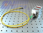
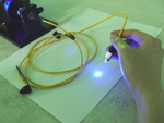
All series CNI Laser modules can be fiber coupled with different core diameter MM fiber or SM fiber. You have to refer to the detailed specs of each laser modules (such as power, stability, noise, size, etc) to decide which one is suitable for your application. We would like to do the coupling job for you.
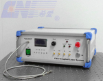
Fiber Coupled Integrated Electronics Laser System
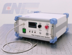
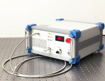
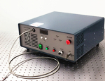
The FC series (Fiber Coupled Laser System) integrates Laser Diode, laser cavity, fiber coupled optics, laser power supply, LD current and crystal temperature control into ONE box. The power is available for 1mW-100W with different dimensions. The characteristics of compact design and convenient functions make it very suitable for pumping, scientific research, industrial and medical applications.
 |
 |
 |
|
FC-X Low Power Levels |
FC-W-A/ B 50W |
FC-W-H 50-100W |
Multi-wavelength Fiber Coupled Laser
Special offer multi-wavelength fiber coupled laser system are designed with integrated electronics and easy operation. 2~6 wavelengths can be combined into one box. USB or RS232 connector is optional. Wavelengths are available for UV-Visible-IR range, lasers include diode and DPSS lasers. The multi-wavelength lasers are widely used for medical, biomedical, and industrial application, etc.
Even Beam Fiber Coupling
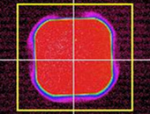
CNI can supply the even beam distribution of laser modules and laser systems, features a flat beam profile with different wavelengths. They are suitable for the fields of medical treatment, ultraviolet curing, fluorescent detection, criminal investigation and scientific research.
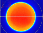
Round Even Beam
Square Even Beam
 |
 |
|
Fiber |
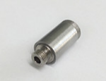
Fiber Collimator |
|
Single-mode fiber with core diameter 4-9 μm Multi-mode fiber with core diameter 50-1000 μm |
Used to collimate the beam at the end of fiber Focus adjustable collimator optional |
Multiwavelength Laser,Fiber Coupled,Red Fiber Coupled Led, Multi-Wavelength Laser
Changchun New Industries Optoelectronics Technology Co., Ltd. , https://www.lasersciences.com