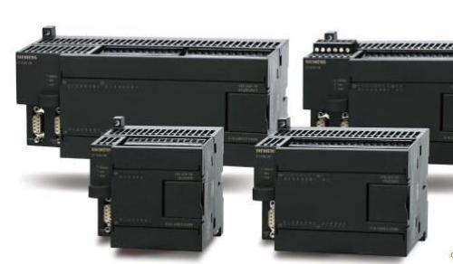
 Programmable controllers are used more and more widely. They are very extensive in modern factories, industrial control, automation, etc. After the programmable controller is put into operation. It can be divided into three phases:
 1, is the programmable controller input sampling phase 2, is the programmable controller and the user program execution phase 3, is the programmable controller output refresh phase above three phases we call him an important stage, to complete the above three important stages This is the basic work of the programmable controller, also known as a scan cycle. The programmable controller plays an important role during the entire operation. The processing unit of the programmable controller, also called the CPU, is a certain scan. The speed is repeated without interruption in the above three phases. Below we will focus on the details of the three stages of the programmable controller:
1. Programmable controller input sampling stage In the input sampling stage, the programmable controller reads all input states and data sequentially by the programmable controller in scan mode, and stores them in the I/O image area. Corresponding unit. After the input sampling ends, it goes to the user program execution and output refresh phase. During these two phases, the state and data of the corresponding cell in the I/O image area do not change even if the input status and data change. Therefore, if the input is a pulse signal, the width of the pulse signal must be greater than one scan cycle to ensure that the input can be read in any case.
2, programmable controller user program execution stage programmable controller in the user program execution stage, the programmable controller is always in the top-down order to scan the user program (ladder). When scanning each ladder diagram, it is always to scan the control circuit formed by each contact on the left side of the ladder diagram, and logically operate the control circuit formed by the contacts in the order of left, right, first, upper, and lower. Then, according to the result of the logic operation, the state of the corresponding bit in the system RAM memory area of ​​the logic coil is refreshed; or the status of the corresponding bit in the I/O image area is refreshed; or it is determined whether to execute the ladder diagram. Specified special function instructions.
During the execution of the user program by the programmable controller, only the state and data of the input point in the I/O image area will not change, while other output points and software devices are in the I/O image area or system RAM storage area. The internal status and data are all likely to change, and the ladder diagram in the above, the programmable controller program execution results will be used in the following ladder diagrams that use these coils or data; instead, row in In the following ladder diagram, the status or data of the logic coil being refreshed can only be applied to the program that is on top of it until the next scan cycle.
If the immediate I/O instruction is used during the execution of the programmable controller program, the I/O point can be accessed directly. Even if the I/O instruction is used, the value of the input process image register will not be updated. The program will directly obtain the value from the I/O module and the output process image register will be updated immediately. This is somewhat different from the immediate input.
3, Programmable controller output refresh stage Programmable controller After scanning the user program, the programmable controller enters the output refresh stage. During this period, the CPU refreshes all of the output latch circuits according to the corresponding status and data in the I/O map area, and drives the corresponding peripherals through the output circuit. At this time, it is the real output of the programmable controller.
Passenger Home Elevator,Small Home Elevator,Elevation Design For Homes
OTSE Elevator Co., Ltd. , http://www.hz-elevator.com