Abstract: This paper introduces the power monitoring system based on the man-machine interface, intelligent electric measuring instrument and motor protector designed and implemented for distributed distribution, feeder and outlet of the intelligent distribution cabinet. The unmanned management function of the interface in the intelligent power distribution cabinet eliminates the tedious operation of on-site personnel on duty, reduces the error of manual operation, improves the quality of power supply and management, and has the advantages of conciseness, practicality, and low investment. Application prospects.
Keywords: human-machine interface; smart meter; power monitoring; intelligent distribution cabinet
0 Preface
The intelligent power distribution cabinet is a distribution cabinet that collects all energy data comprehensively, provides high-precision measurement data for the terminal energy monitoring system, and reflects the power parameters and power quality data in real time through the display unit, and communicates with the background control system through digital communication. In order to achieve effective management of the real-time monitoring and operation quality of the entire distribution system, and as the development trend of the intelligentization of the current distribution industry, the power monitoring system is a very important component of distribution automation control. The main functions include: data acquisition and Display, data record, export, real-time display of equipment operating status, records, etc.
This paper takes the electric power monitoring and management system of an intelligent distribution cabinet of an electric appliance company as an example, and proposes to design a set of intelligent intelligent power monitoring and management system using touch screen, smart meter, motor protector and circuit breaker module, etc.[1] In the circuit of feeders, feeders and outlets, real-time monitoring and management of the operating parameters and operating conditions of the electrical equipment for each circuit of the distribution cabinet.
1 Project introduction
The power monitoring system can monitor the power usage of each loop device by using the power meter, display and store in real time through the centralized acquisition and display terminal, and can derive data of a working cycle, which is convenient for system and power data analysis, and can be used for power distribution. The cabinet provides the basis for analysis equipment operation status and power usage. The intelligent power distribution cabinet power monitoring system project is based on the user's demand for on-site power distribution cabinet incoming line, feeder line, outgoing line equipment, and power usage monitoring. The Kunlun on-state touch screen is used. TPC1062K and Acrel Intelligent Instrument PZ72L-E4/KC, PZ80L-E4/KC and motor protector ARD2F-100A/CKQ, to realize the three-phase operation of the power distribution equipments of the intelligent distribution cabinet such as the incoming line, feeder line and outgoing line Real-time monitoring and display of voltage, current, active power, reactive power, apparent power, and energy data, data storage, export function, real-time display of the on-off status of the circuit, and overload, unbalance, underload, and grounding of the motor equipment Failures such as fault alarming and recording can not only ensure the normal operation of the intelligent power distribution cabinet, but also can enter the line of the distribution cabinet. Line, real-time monitoring outgoing circuit management.
2 user needs
Through monitoring and management of the power distribution cabinet and understanding the operation status and power usage of the equipment, the following requirements are proposed for the designed power monitoring system:
real-time display:
Line cabinet: Collect the voltage, current, power and energy of the PZ80L-E4/KC intelligent instrument of the incoming line cabinet in real time through the touch screen, and intuitively show the load of the main power line cabinet;
Feeder cabinet: It mainly collects the voltage, current, power and power parameters of the feeder cabinet circuit, which is convenient for the user to know in real time the power consumption condition of the external required power supply;
Outgoing cabinets: Acquire the AC current, voltage, power and other parameters of the single loop of the outgoing cabinet through the PZ72L-E4/KC AC meter, and use the motor protector ARD2F to perform data monitoring and protection on the outgoing loop motor;
Curve analysis: real-time display of current (or power) real-time curve trend graph of each electrical cabinet;
Event alarm: realize the over-limit alarm of voltage, current, power, frequency, power factor and other parameters of incoming cabinets, feeder cabinets, outlet cabinets;
Energy management: Complete the power parameter collection function of each instrument of the loop. You can query the active power value, reactive power value, power consumption (KWH), power factor, current and voltage value of each phase of each loop at the historical time. Report storage The shortest time is 1S, and automatically generate electricity reports that meet customer management requirements. The report can realize real-time energy query on the touch screen.
Data export: The power parameters of each instrument are automatically and manually exported according to the time required by the customer, and exported to the U disk in Excel format for customer's statistics and printing.
3 Design Plan
3.1 Reference Standard
GB/T3797-2008 "Electrical Control Equipment"
GB/T11022-1999 "Shared Technical Requirements for High Voltage Switchgear and Control Equipment Standards"
20077566-Q-604 "Safety requirements for industrial automation products - Part 1: General rules"
20077556-Q-604 Safety Requirements for Industrial Automation Products - Part 10: Safety Requirements for Recording Instruments
GB/T 16656.46-2010 "Industrial Automation System and Integration and Product Data Expression and Exchange"
DL/T 814-2002 "Functional Specifications for Distribution Automation Systems"
DL/T634-2002 "Standards for Remote Telemetry Tasks for Telecontrol Equipment and System Transmission Protocols"
DL/T 814-2002 "Functional Specifications for Distribution Automation Systems"
DL/T645-1997 "Multifunction Wattmeter Communication Protocol"
3.2 System Introduction
The entire system equipment mainly includes man-machine interface, intelligent instrument PZ72L-E4/KC, PZ80L-E4/KC, motor protector ARD2F-100A/CKQ and switching power supply, and the incoming circuit and feeder circuit of the power distribution cabinet through shielded twisted pair cables. Each instrument of the outlet loop is connected to the centralized collection and display terminal. It collects, displays real-time data, saves parameters, and records faults in the field to realize the power monitoring and management of the intelligent distribution cabinet system. The overall architecture of the system is shown in Figure 1 below.
.png)
Figure 1 Overall system structure
3.3 Equipment Selection
Application scenario
product demand
Product number
product description
Incoming circuit
Line switch
.png)
PZ80L-E4/KC
Measurement of electrical parameters such as three-phase current, three-phase voltage, active power, reactive power, power factor, and active energy
Feeder loop
Low-voltage motor protection
.png)
ARD2F
Motor start timeout, overload, stall, phase failure, unbalance, underload, ground/leakage, blockage, overvoltage, undervoltage, winding overtemperature protection
Outlet loop
Low pressure outlet
.png)
PZ72L-E4/KC
Measurement of electrical parameters such as three-phase current and voltage, active power, reactive power, apparent power, power factor, and active energy
Power monitoring circuit
touch screen
.png) TPC1062K
TPC1062K
Adopt 10.4-inch high-brightness LCD display, four-wire resistive touch screen, pre-installed MCGS embedded configuration software, with powerful image display and data processing functions
4 system function
The upper computer adopts the touch screen TPC1062K, connects with the field device through the touch screen [2], and carries out database variable configuration, interface design, etc. in the touch screen, and completes the monitoring of the field intelligent instrument PZ72L-E4/KC, PZ80L-E4/KC in the upper computer. ARD2F motor protectors, circuit breakers and other power distribution equipment power conditions and operating conditions.
4.1 System Diagram Display
Real-time display of the operating status of the electrical equipment in each circuit of the intelligent power distribution cabinet on the touch screen, which is convenient for real-time understanding of the status of field equipment, timely processing of faults occurred, and realizing the device's closing and closing control on the touch screen to achieve remote remote control operation. The figure shows the interface as shown in Figure 2.
.png)
Figure 2 System Diagram Display Interface
4.2 Data Acquisition Display
Touch screen collection Intelligent distribution cabinet incoming circuit PZ80L-E4/KC smart meter, feeder circuit PZ72L-E4/KC smart meter, outlet circuit motor protector ARD2F-100A/CKQ and PZ72L-E4/KC AC power meter , Three-phase voltage, three-phase current, frequency, power factor, active power, reactive power, apparent power, energy and other parameters, and accurately displayed in the human-machine interface in real time, to facilitate users to understand the system operating parameters and energy Consumption monitoring management, specific data shown in Figure 3 to Figure 5.
.png)
Figure 3 Inlet loop data display interface
.png)
Figure 4 feeder loop data display interface
.png)
Figure 5 Outlet loop data display interface
4.3 Curve display
Power monitoring system will be intelligent power distribution cabinet into the circuit PZ80L-E4/KC smart meter, feeder circuit PZ72L-E4/KC meter, outlet circuit low voltage motor protector ARD2F and PZ72L-E4/KC smart meter [3] The three-phase current is transmitted to the man-machine interface in the form of a curve to provide the user with a real-time curve, which helps the user to understand the power condition of the device and facilitate the user to know the power consumption equipment in real time. The specific curve interfaces are shown in FIGS. 6 to 8 .
.png)
Figure 6 Line Cabinet Curve Display Interface
.png)
Figure 7 Feeder Cabinet Curve Display Interface
.png)
Figure 8 outlet cabinet curve display interface
4.4 Data Storage
The system collects the instrumentation data of the incoming circuit, feeder circuit, and outgoing circuit of the distribution cabinet and queries the historical data according to the time period. The time interval is selected to accurately query the historical data collected by the system, and the faults occurring during the operation of the outgoing loop motor are also performed. Real-time save, the query result is displayed in the touch screen save data construction, which is convenient for the user to know the running parameters and running status of the equipment in real time. At the same time, the data can be exported, which is convenient for understanding the historical running status of each equipment. The save data interface is as shown in Figure 9 Figure 10 shows.
.png)
Figure 9 save the parameters of the interface
.png)
Figure 10 Energy Save Screen
4.5 Fault Record
Through the touch screen's telemetering, the alarms are realized for parameters such as voltage, current, power, frequency, power factor and other parameters of the intelligent distribution cabinet's incoming circuit, feeder circuit, and outlet circuit, and real-time recording is performed to facilitate the user's understanding. Field equipment operating parameters exceed the set value status and equipment operating conditions, event alarm recording interface as shown in Figure 11 below.
.png)
Figure 11 event alarm record interface
5 System Features
Perfect data collection function to realize the data collection, display and equipment operation status analysis of all electrical equipment in the intelligent distribution cabinet. The data collection of the distribution cabinet is realized by the communication module, and the data is transmitted from the communication collection to the background monitoring.
Safe operation monitoring, the operator uses the touch screen system man-machine interface to monitor the equipment running status of the incoming line, feeder line, and outlet circuit of the intelligent distribution cabinet, and real-time display, which facilitates the analysis and processing of the equipment when the operating status changes.
The system is reliable in operation, and provides the alarm recording display of the operating status of the main equipments of the intelligent distribution cabinet incoming line, feeder line, and outgoing line loop. It is convenient for the operator to deal with the fault alarm and the emergency status.
Realize remote control, switch on and off the line on the touch screen, reduce the labor intensity of on-site operation personnel, and improve the level of safe operation [4].
6 Conclusion
As a precision power distribution cabinet, intelligent power distribution cabinets have the functions of operation management and safety management in addition to distribution management. They can comprehensively monitor various operating parameters of the system and effectively improve the reliability of the entire distribution system. The design and application of the power monitoring system in the distribution cabinet, the configuration of the network power meter in the intelligent power distribution cabinet, can conveniently and real-timely monitor the power status and operation status of each circuit equipment in the distribution cabinet, and manage the on-site power equipment in a unified manner. It eliminates the tedious work of staff to record and operate on the site and reduces the workload of personnel. At the same time, the power monitoring system in the intelligent distribution cabinet manages and analyzes the historical operating data of various electrical equipment. The entire system not only ensures the field equipment. The safe operation has high system reliability and improves the distribution quality and management level of the distribution cabinet. Therefore, the application of the power monitoring system in the intelligent distribution cabinet fully reflects the advantages of intelligent power distribution and has a wide range of Application prospects.
references:
[1]. Zhou Zhongzhong. The product selection and solution of smart grid user end power monitoring and power management system [M]. Beijing. Machinery Industry Press. 2011.10
[2]. Kunlun modality touch screen MCGS elementary and intermediate course. 2013.4
[3]. Liu Meiji. Intelligent power monitoring system for distribution cabinets [J]. Electric Automation Technology, 2007(3): 102~105.
[4].Peng Liangchao, Liu Jiefang et al. Intelligent Monitoring System for Distribution Cabinets[J]. Electronic Products Technology, 2010(8):183~185.
Single Housing Pressure Filter
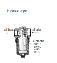
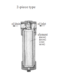
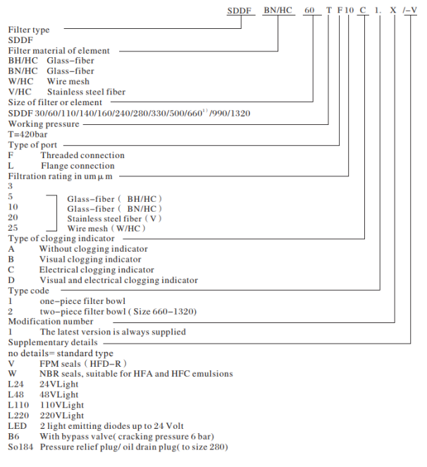
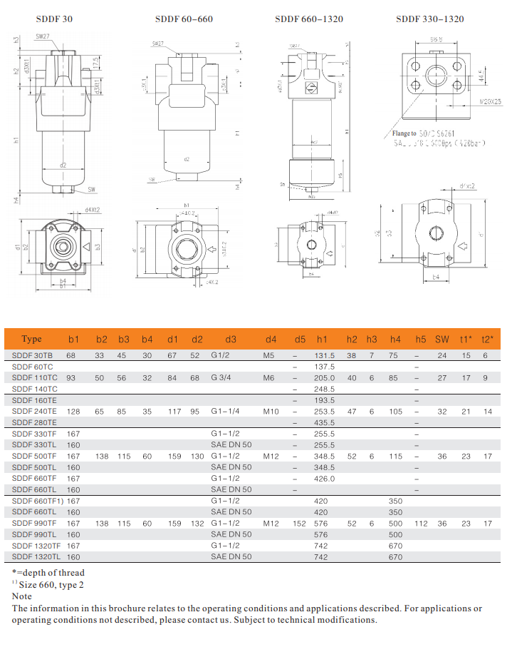
SDDF series filters consist of a filter head with a screw-in filter bowl. 1-piece filter bowl for size 660 and below; 2-piece filter bowl for size 990 and above. Standard filters are without bypass valve.


Material
SDDF series
Filter head: nodular cast iron Filter bowl: carbon steel
Seals:NBR
Special type
-With bypass valve
-Oil drain screw up to SDDF280
-Seals in FPM
Accessories
-Visual and (or) electrical
clogging indicator,clogging indicators should be fixed with corresponding torque values. (See Spare parts and maintenance list)
-Flange connection
-SAE-flange connection


Pressure Filtration,Single Housing Pressure Filter,Single Housing High Pressure Filter,Single Housing Pressure Filtration
Xinxiang Shengda Filtration Technique Co., Ltd. , https://www.shengdafiltration.com