The electric valve positioner is one of the key attachments of the pneumatic regulating valve. Its role is to change the electrical signal output by the regulating device into the gas signal that drives the operation of the regulating valve. It has a valve positioning function, which overcomes the friction of the valve stem and overcomes the unbalanced force caused by the change of the medium pressure, enabling the valve to follow quickly and responding to the control signal output by the regulator to realize the quick positioning of the regulating valve. , improve its adjustment quality. With the development of smart meter technology, microelectronics technology is widely used in traditional instruments, greatly improving the function and performance of the instrument. Its application in the electric valve positioner has made a big leap in the performance and function of the smart positioner.
Second, the comparison of intelligent electric valve positioner and traditional positioner
2.1 The working principle of the traditional electric valve positioner
After several decades of development of electric valve positioners, the company's products are not all the same, but the basic principles are roughly the same, the following drawing sketches to illustrate. The basic structure is shown in Figure 1:
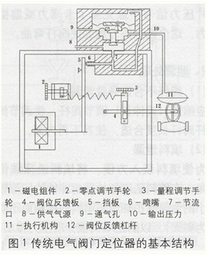
Feedback valve feedback valve position changes, when the input signal generated by the electromagnetic torque and the positioner feedback system generates the same moment, the positioner balance system is in equilibrium, the positioner is in a stable state, the input signal and the valve at this time The bit corresponds to the proportional relationship. When the input signal changes or the fluid force of the medium changes, the equilibrium state of the force balance system is broken, and the force generated by the magnetoelectric assembly and the force generated by the feedback loop due to the position change of the valve stem are in an unbalanced state. The nozzle and the baffle act to change the output pressure of the air source of the positioner. The change of the pressure in the air chamber of the actuator pushes the actuator to move the valve rod to the new position, which corresponds to the input signal again and reaches a new equilibrium state.
When changing the structure of the feedback lever of the positioner (such as the cam curve) during use, the positive, negative, and flow characteristics of the regulating valve can be changed and the performance of the regulating valve can be improved.
2.2 Working principle of intelligent electric valve positioner
Although the intelligent electric valve positioner and the traditional positioner have basically the same control law, they compare the input signal with the position feedback and adjust the output pressure signal. However, the intelligent positioner and the traditional positioner on the actuator are completely different, that is, they are totally different in the way of operation. The intelligent positioner takes the microprocessor as the core and uses a new type of piezoelectric valve instead of the nozzle and bezel pressure regulating system in the traditional positioner to realize the adjustment of the output pressure.
At present, there are many manufacturers of intelligent electric valve positioners. Siemens' SIPATT PS2 series of intelligent electric valve positioners are typical and representative. The SIPART PS2 series positioners are used as an example to illustrate the working principle of intelligent positioners. To explain, the basic structure is shown in Figure 2:
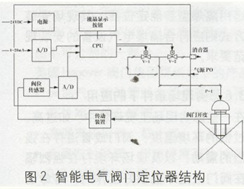
The specific working principle is as follows:
The actual opening signal of the valve picked up by the valve stem position sensor is converted into a digital coded signal by A/D conversion, and the digital code of the input (setting) signal of the positioner is compared with the CPU, and the deviation values ​​are calculated. If the deviation value exceeds the positioning accuracy, the CPU output command causes the corresponding open/close piezoelectric valve to act, that is, when the set signal is greater than the valve position feedback, the boosted piezoelectric valve V1 opens, and the output air source pressure P1 increases. Large, the increase in air pressure in the actuator is the increase in the opening of the valve, reducing the deviation between the two; if the set signal is less than the feedback in the valve position, the exhausted piezoelectric valve V-2 is opened, and the output air pressure is reduced through the exhaust of the muffler. P1, the reduction of the pressure in the air chamber of the actuator is the decrease of the valve opening, and the deviation between the two is reduced. It is through the control of the piezoelectric valve by the CPU to adjust the output air pressure to achieve a new balance between the input signal and the valve position.
2.3 The novelty of the intelligent electric valve positioner on the pressure regulation of the output air source
1) The output pressure regulation adopts PID pulse width modulation (PWM) technology, which is fast and accurate. Because the control of the piezoelectric valve by the CPU is controlled by a five-step switching procedure, the pressure of the output air source can be accurately and quickly controlled. The control algorithm generally adopts digital PID adjustment method. The CPU performs PID calculation according to the magnitude and direction of the deviation between the input signal and the valve position, and outputs a PWM pulse width modulation pulse signal to control the opening and closing of the piezoelectric valve. Because the width of the pulse corresponds to the increment of the air pressure at the output of the positioner, the pressure output P1 of the air source can be quickly and accurately changed. When the deviation is large, the positioner outputs a continuous signal, rapidly and continuously changes the size of P1. When the deviation is small, the positioner outputs a pulse signal with a smaller pulse width, which changes the size of P1 intermittently and slightly. When the deviation is very small (into the deadband), there is no pulse output and the valve position works stably.
2) The adoption of new piezoelectric valve devices ensures high-precision control. The main element of a piezo valve is a piezo-flexible on-off valve, also known as a silicon micro-controlled valve. Because of its small mass, the inertia of the switch is very small and it can perform very high switching frequencies, thus acting as a high-frequency pulse valve. The output air pressure P1 is controlled to drive the actuator and high valve positioning accuracy can be achieved.
3) The valve position feedback element has high positioning accuracy and long life. The valve position feedback element is a conductive plastic potentiometer with simple structure, high precision and high reliability. It converts the linear or angular displacement of the actuator into a resistance signal, so that the valve position can be accurately detected and the valve can be easily zeroed. , Full-scale and valve flow characteristic curve positioning.
2.4 Features of Intelligent Positioner
Due to the use of new types of control elements such as conductive plastics and piezoelectric valves, the positioning of the valve can be achieved with high precision. Due to the use of micro-processing, the positioner can be adjusted and the application range can be greatly improved. The main features are:
1) It is easy to install; it can be adjusted automatically. The configuration is simple and flexible, and it is very convenient to set the positive and negative action of the valve, flow characteristics, stroke limitation or split-range operation.
2) The gas consumption of the positioner is minimal. The nozzle and baffle system of conventional positioners are continuous air-consuming elements. Because the intelligent positioner uses a pulsed piezoelectric valve instead of the nozzle and baffle system of the traditional positioner, and the five-step pulsed piezoelectric valve control method can achieve fast and accurate positioning of the valve. The intelligent positioner exhausts air only when the output pressure is reduced, so it is in a non-consumed state for most of the time, and its total air consumption is 20L/h, which is negligible compared to a conventional positioner.
3) It has intelligent communication and on-site display functions to facilitate maintenance personnel to check and repair the positioner's working condition.
4) Locator and valve can be installed separately. Because the position feedback element of the intelligent positioner is a potentiometer, that is, the valve position information is transmitted by the electric signal, and the characteristics of the valve can be set in the CPU in the field. Therefore, the method of setting the stroke position detection device externally separates and installs the valve position feedback assembly from the positioner itself. The stroke position detection device is located on the actuator and the positioner is installed at a certain distance from the actuator, as shown in Figure 3:
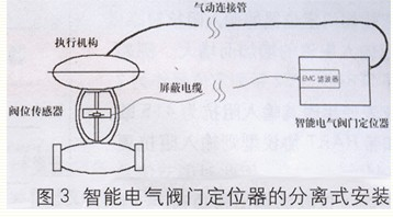
This greatly expands the range of use of the positioner. For example, it can be applied to actuators for non-standard structures such as large dampers and gates and actuators for oversized stroke structures (there are a large number of such applications). It is the combination with the intelligent electric valve positioner that greatly improves the control and positioning accuracy of such devices.
5) The stroke detection device can also use non-contact position sensor for bad site. Such as the application of the valve in the environment of strong vibration, high and low temperature and nuclear radiation, to avoid the impact of bad environment on the locator to ensure the reliable use and life of the locator.
6) Rich self-diagnosis function. Not only can the malfunction of the positioner itself be self-diagnosed, but also the performance of the regulating valve and the actuator can be quantitatively measured and diagnosed. Such as the valve stroke change detection, the measurement of the valve's extreme position changes, can diagnose the valve's wear condition; The measurement of the valve's positioning time can diagnose whether the positioning period is appropriate, whether it will cause oscillation; also can be sealed on the pneumatic actuator, etc. Diagnose it to provide a scientific basis for valve maintenance.
7) It is very convenient to carry out safety test, test and test operation. Especially in the safety instrument system where the valve has a high requirement for reliable operation, the safety and effectiveness of the valve execution of the SIS safety instrument system can be verified online. See Reference 2.
Third, the actual use of the problem should be noted
Although the smart locator is simple to use and powerful, it should pay attention to some problems in engineering applications so that it can work reliably, exert better control, and extend its service life.
3.1 Positioner 2/4 wire connection method selection
Due to the high input impedance of the smart valve positioner, it increases with the input current. For example, when Siemens SPRART PS2 series positioner is used as 2-wire meter, its input impedance is 415 ohms, and with HART protocol, the input impedance is larger, which is about 440 ohms. Therefore, there is a higher requirement for the load capacity of the adjustment signal. . Under normal circumstances, the digital adjustment instrument output load capacity is less than 300 ohms, so when using the intelligent electric valve positioner must check the regulator output control signal with load capacity, should be greater than 500 ohms, in order to guarantee a large opening The normal operation of the locator. The author once directly driven the SPRART PS2 intelligent electric valve positioner in the output circuit of a DCS system, and can only drive a current of 18 mA, that is, it can only satisfy the stroke opening within 87.5%. And in the case of communication, the maximum current will be further reduced, seriously affecting the positioning requirements at large opening. In view of this, the following solution should be considered when the regulator output control signal has insufficient load capacity:
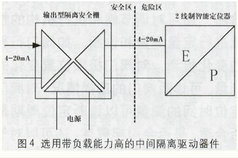
1) Set signal isolation devices in the input signal loop to increase the load capacity of the control signal. That is, the intermediate isolation driving device with high load capacity is selected, and the device carrying capacity should be greater than 500 ohms. If the site is an explosion-proof place, you can use an isolated barrier with high load capacity, such as the MTL3000 series isolation barrier, as shown in Figure 4:
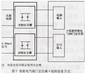
2) Use 4-wire connection to reduce the input impedance of the input circuit of the smart positioner, as shown in Figure 5. Since the power supply circuit is increased, the input impedance of the signal path of the smart positioner will be greatly reduced. , About 250 ohms, in line with the load requirements of most regulator output circuits.
3.2 Reasonably set the positioner's action dead zone
The setting range of dead zone for general smart positioner is between 0.1 and l0.0%. The smaller the dead zone setting, the higher the positioning accuracy, but the more frequent the movement of the corresponding piezoelectric valve and the feedback connecting rod and other moving parts, sometimes even causing the valve to oscillate, increasing the mechanical wear and affecting the life of the positioner and the valve. The dead zone setting of the locator should not be too small, it should be set in conjunction with the specific process control accuracy requirements, generally not less than 0.5%.
3.3 Reasonably set the control period
The control period of the control system should be set reasonably in combination with the characteristics of the regulator and the object being regulated. The control response time of the general smart positioner itself is 1.5s, so it is appropriate that the regulator output change period is set to about 1.0s.
3.4 Selection of Intelligent Locator Traffic Characteristics
Smart Locators all have flow feature selection settings. However, in actual use, it is necessary to reasonably determine the flow characteristics and process specific requirements of the valve being equipped. The flow characteristics of valves used in general positioners are determined by the processing characteristics of the spool. The spool has linear, equal percentage, quick opening and other flow characteristics. If the process requirements are consistent with this, the output characteristics of the smart positioner should be selected as a linear output, so that the overall valve flow characteristics are in line with the original design requirements.
When in actual use, if the valve core does not have flow characteristics suitable for the process requirements, the overall flow characteristics of the valve can be changed by changing the output characteristics of the valve positioner. Such as: you can modify the intelligent positioner to equal percentage of output, the valve with a linear spool to equal percentage flow characteristics of the valve to use; or modify the intelligent positioner to reverse the same percentage of output, can equal percentage valve spool Adjust the valve for linear flow characteristics to use.
3.5 Application in explosion-proof environment
In the explosion-proof environment should be used intrinsically safe or flameproof intelligent locator. In addition, attention should be paid to the matching between the input impedance of the smart positioner and the load capacity of the safety-related device when wiring. If an intrinsic safety circuit is constructed, it is best to use an output type isolation barrier with an overload capacity of more than 500 ohms. If a Zener barrier is used, a 4-wire connection method should be used to reduce the input impedance of the positioner signal loop. If a flameproof intelligent positioner is selected, the on-site installation method shall meet the requirements for the installation of explosion-proof electrical equipment.
3.6 Application under harsh field conditions
In some severe field conditions, such as excessively high or low ambient temperature, there is strong vibration in valves or pipelines, and there is strong radiation and strong electromagnetic interference in the on-site environment. Intelligent valve positioners are not well installed on valves. If you work, your lifespan will be greatly reduced. At this point, the valve position sensor and intelligent positioner can be installed separately. A valve position sensor (generally a simple element such as a linear resistance sensor) is mounted on the valve, and the intelligent positioner itself can be separately installed at a distance from the valve in a condition with a better working environment, as shown in FIG. The valve position sensor and the intelligent positioner are connected through a cable. The pneumatic output of the intelligent positioner is connected with the actuator through the pneumatic connection pipe, so that the valve can be reliably positioned and controlled. Shielded cables should be used for the cable connection and EMC filters should be used in the smart positioner to suppress disturbances caused by harsh environments.
Fourth, summary
Thanks to the adoption of CPUs and new types of devices, the performance of smart electric valve positioners has made a big leap compared with traditional valve positioners. The intelligent electric valve positioner has higher positioning accuracy, wider application range, and more convenient and reliable use. However, in the specific application, the type of the positioner should be reasonably selected in terms of compliance with safety requirements, better control effects, matching with the control loop, adaptation to special environmental requirements, and prolonged service life, and its function parameter setting and adjustment should be performed. school.
CNC Machining is a manufacturing process where computers run programs that control how the machines will manufacture parts. These CNC Programs using CNC Software can control everything from the motions the machine makes to spindle speed, turning coolant on or off, and much more. The computer language used to program CNC Machines is called [G-Code". To make it easier, g-code is seldom written by hand. Instead, visual programming tools called CAM Software are used to create the g-code.
Machined parts are often chosen when manufacturing must result in high precision or quality, or when the materials are particularly tough and hard to work.
There are many different kinds of CNC Machine including 3D Printers, CNC Mills, CNC Lathes, CNC Lasers, Water Jets, Electronic Discharge Machines (EDM`s), CNC Routers, and more.
Benefits of CNC machining
1) Lower labour costs
2) CNC increases production choices
3) No need for extensive skills or experience
4) Reproduce your product range endless times
5) No costly prototypes required
We have made many aluminum parts by CNC process, these parts are commonly used in industry, automotive, consumer, electrical field. specially, we ever made kinds of componets that used in automotive field and have the 2nd process treatment( such as anodization, Powder Coating, spary coating), we can ensure the best quality sample with lower price to you to make sure you are ok with sample and glad for production.
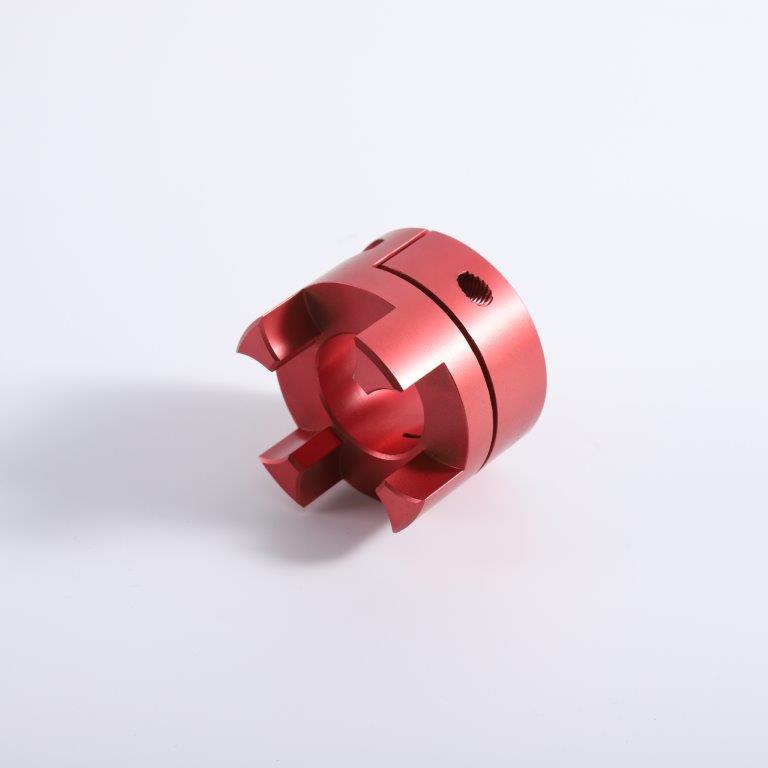
Cnc Machining,Cnc Machining Services,Custom Cnc Machining,Cnc Cutting Services
Suzhou FCE precision electronics Co., LTD , https://www.fukeyifcesz.com